Machine Design Project
For this Machine Design project, I, along with a team of 4 other students, designed and built an arcade button-pressing mechanism capable of rapidly and accurately targeting multiple buttons using a single motor. This involved developing a low-inertia linkage system in SolidWorks, optimizing speed and torque through an inertia-matched transmission, and integrating sensors with closed-loop PID control on an Arduino to ensure precise positioning. We fabricated components in the machine shop, assembled the device to meet tight tolerances, and implemented safety features such as limit switches and hard stops. Through iterative testing and optimization, we refined the mechanism to achieve reliable, high-speed performance under competition conditions.
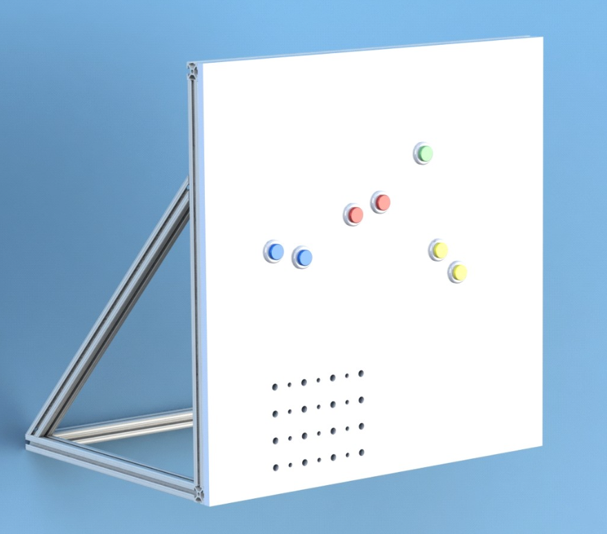
Design Requirements & Constraints
Below is the board to which our mechanism would mount. Note that the button placement and mounting holes for our mechanism served as the main constraints for our design. The button locations were used to determine and calculate optimal transmission angles for our mechanism which served as the foundation for our design.
- Machine Design Requirement: The device must press the buttons as many times as possible in 1 minute using a DC motor in a PID controlled system. The red, blue and yellow buttons must be pressed with the provided acrylic actuator piece.
- Performance Score Requirement: The performance score is designed as the number of points accumulated at the end of the round. Points are awarded when a button is successfully pressed. The score should be maximized.
- Financial Constraint: Teams are provided with a kit of specified materials. Each team has a budget of $100 to source their transmission and button actuation devices.
- Transmission Angle Constraint: The transmission angle deviation from the ideal transmission angle of 90 degrees must not exceed 60 degrees.
- Volume Constraint: The mechanism should be as small as possible. The smallest rectangular box that encases your device must not exceed 15,000 cubic inches.
- Safety Requirement: The mechanism must be safe, with all sharp edges filleted; threads on bolts should not protrude more than 1.5 times their diameter.
- Craftsmanship Constraint: The mechanism must be well machined with a good surface finish and be aesthetically pleasing.
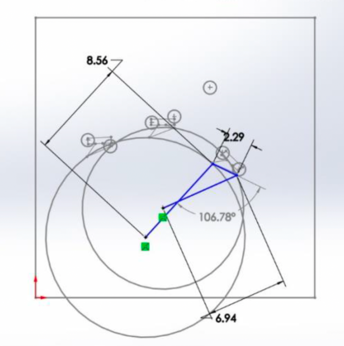
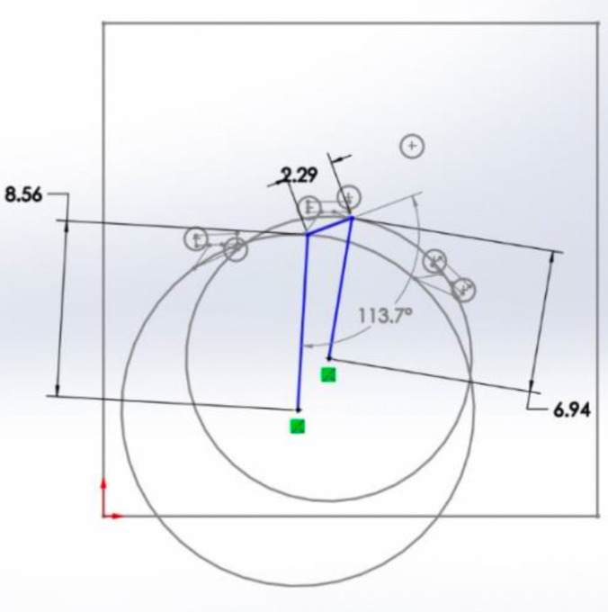
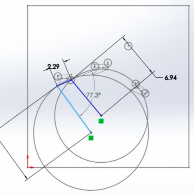
Transmission Angle Design
Utilizing SolidWorks, I constructed a 2-D layout of the 4-bar linkage mechanism that would be able to press the 3 button pairs. I engaged in an iterative design process optimizing transmission angles, ground pivot points, and coupler geometry.
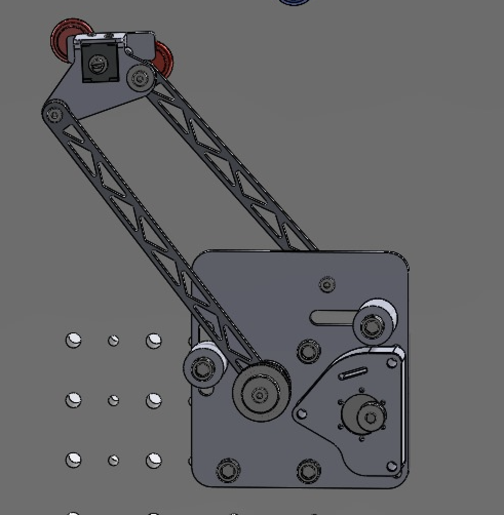
Mechanism Design & Manufacturing
The transmission angle design was used to inform the length of our linkages, the ground pivot locations and coupler geometry. The full assembly of our mechanism was modeled within SolidWorks including the DC motor, shoulder bolts, sleeve and oil bearings, linkages, ground pivots, hard stops, transmission timing belt gears, and solenoid.
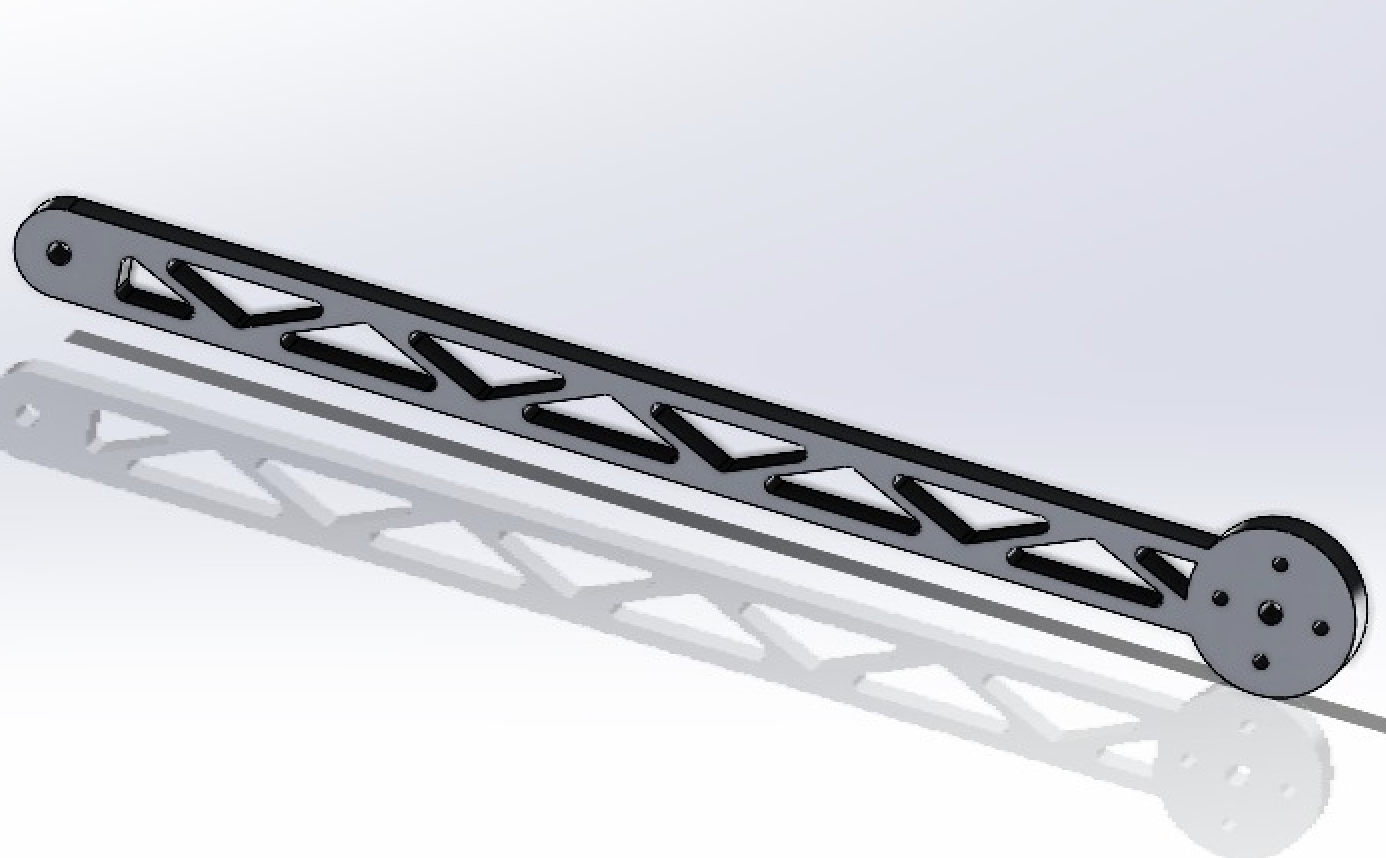
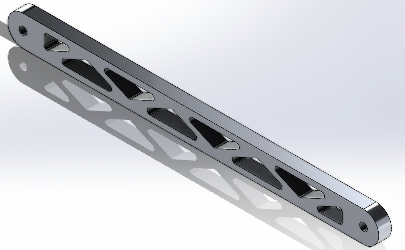
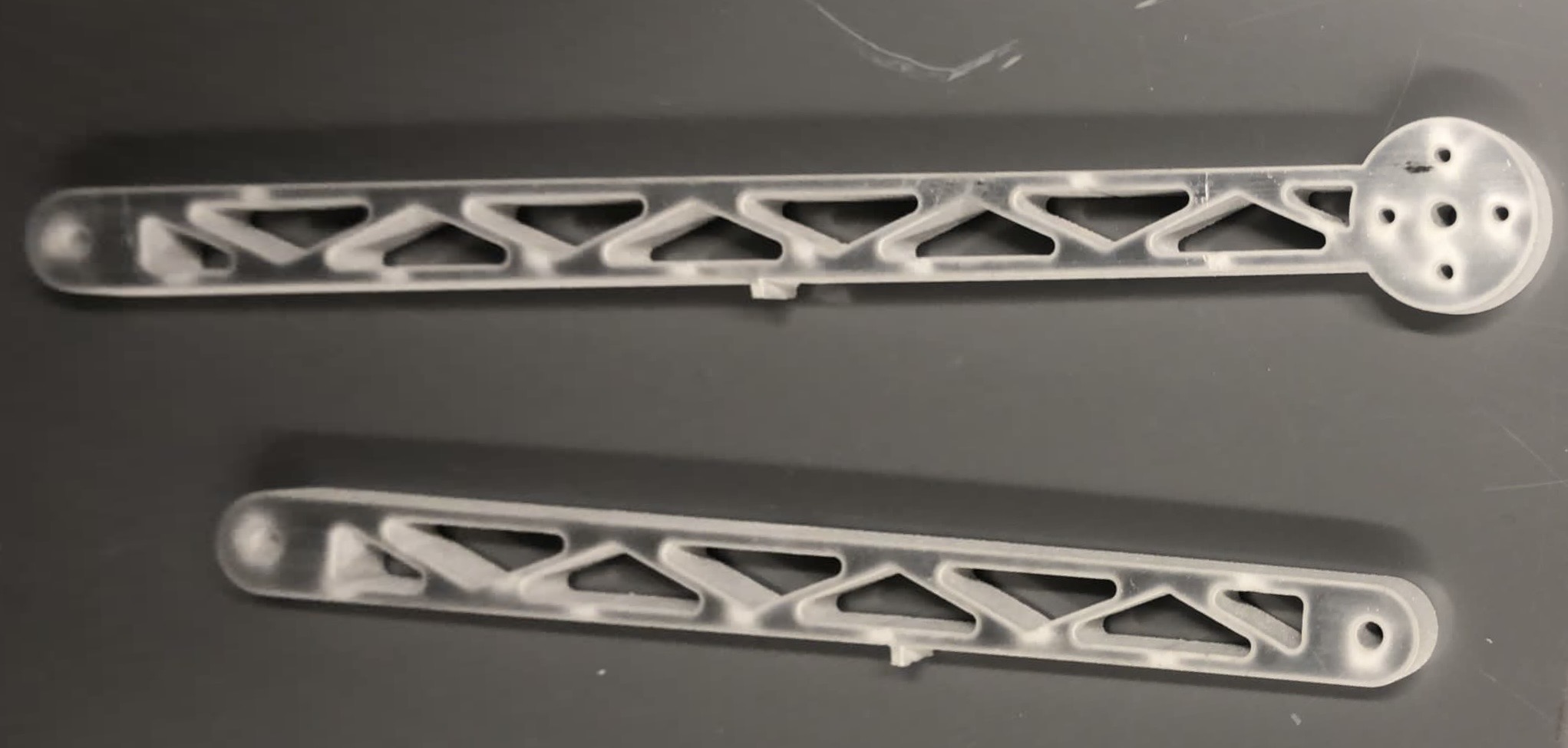
Linkages
The linkage geometry was designed and modeled within SolidWorks. The design was optimized for structural stability and the minimization of weight. This is seen by the trusses built into the interior of the links which maintain the integrity of the part while removing mass. Note that FEA was conducted on the linkages factoring in the worst case loading. These parts were machined from the provided aluminum sheet using a Waterjet and CNC Mill.
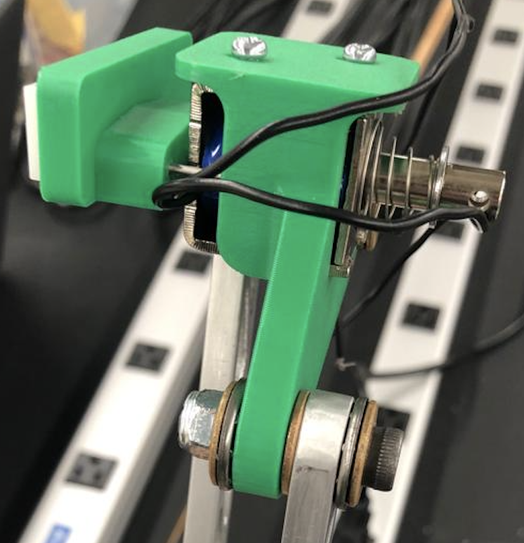
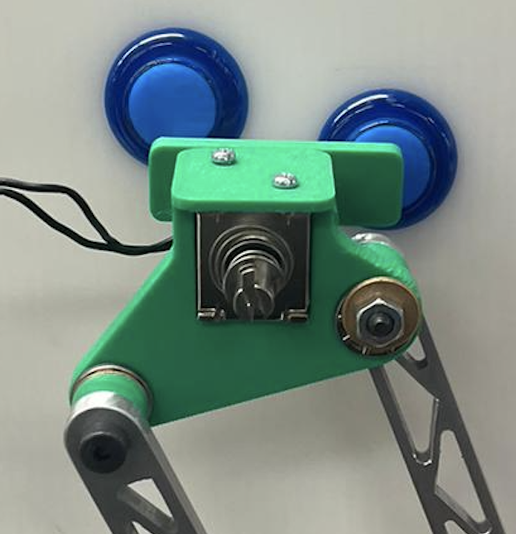
Coupler
The coupler was designed in SolidWorks to hold our solenoid button actuator and the provided acrylic button presser.
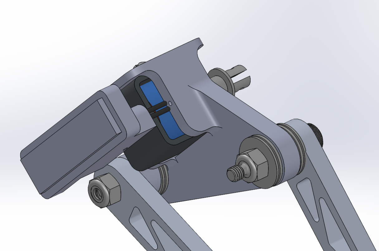
The coupler was 3D printed with PLA due to its complex geometry. This also worked to significantly reduced its weight when compared to aluminum alloy. The solenoid was fixed in place with mounting screws. The acrylic button presser was mounted to the solenoid via a press fit and stabilized with two thin steel rods.
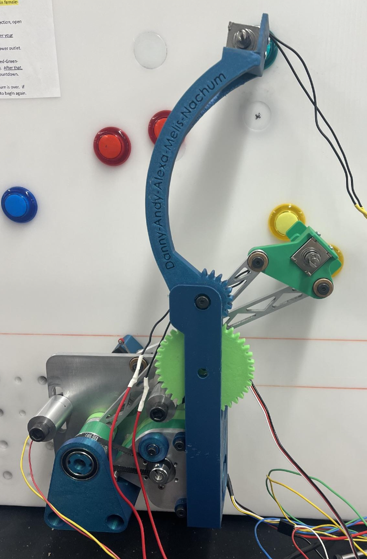
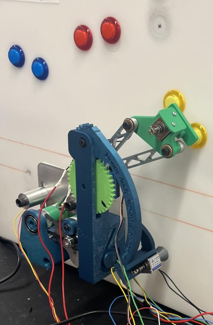
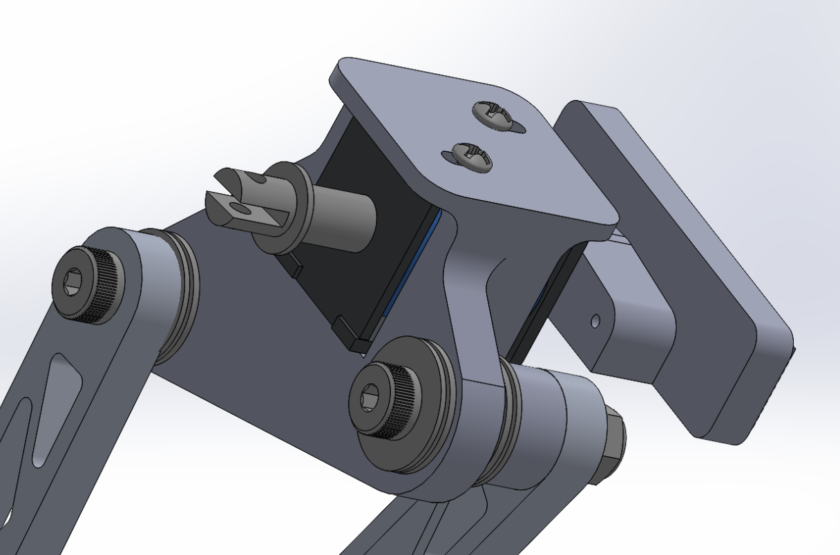
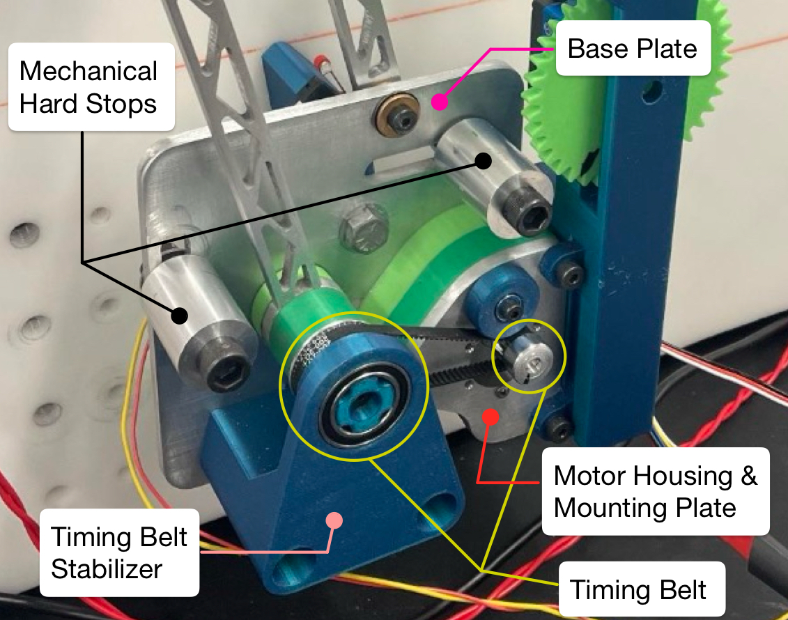
Ground Plate & Motor Components
The base plate, mechanical hard stops and motor mounting plate of our mechanism were machined via Waterjetting and CNC Milling. They were assembled to the mounting board as displayed below.
We note that the transmission ratio required to actuate our mechanism was calculated via inertia matching based upon the weight, dimensions and inertial centers of the linkages and coupler assembly (solenoid included). We achieved a transmission ratio of 2.5. For an added safety factor we sourced our transmission components for a ratio of 3. Note a timing belt was chosen as it was relatively inexpensive and provided us with mounting flexibility. Additional components such as spacers and stabilizers were designed and FDM printed to refine the operation of our timing belt transmission.
Arduino PID Controller State Machine
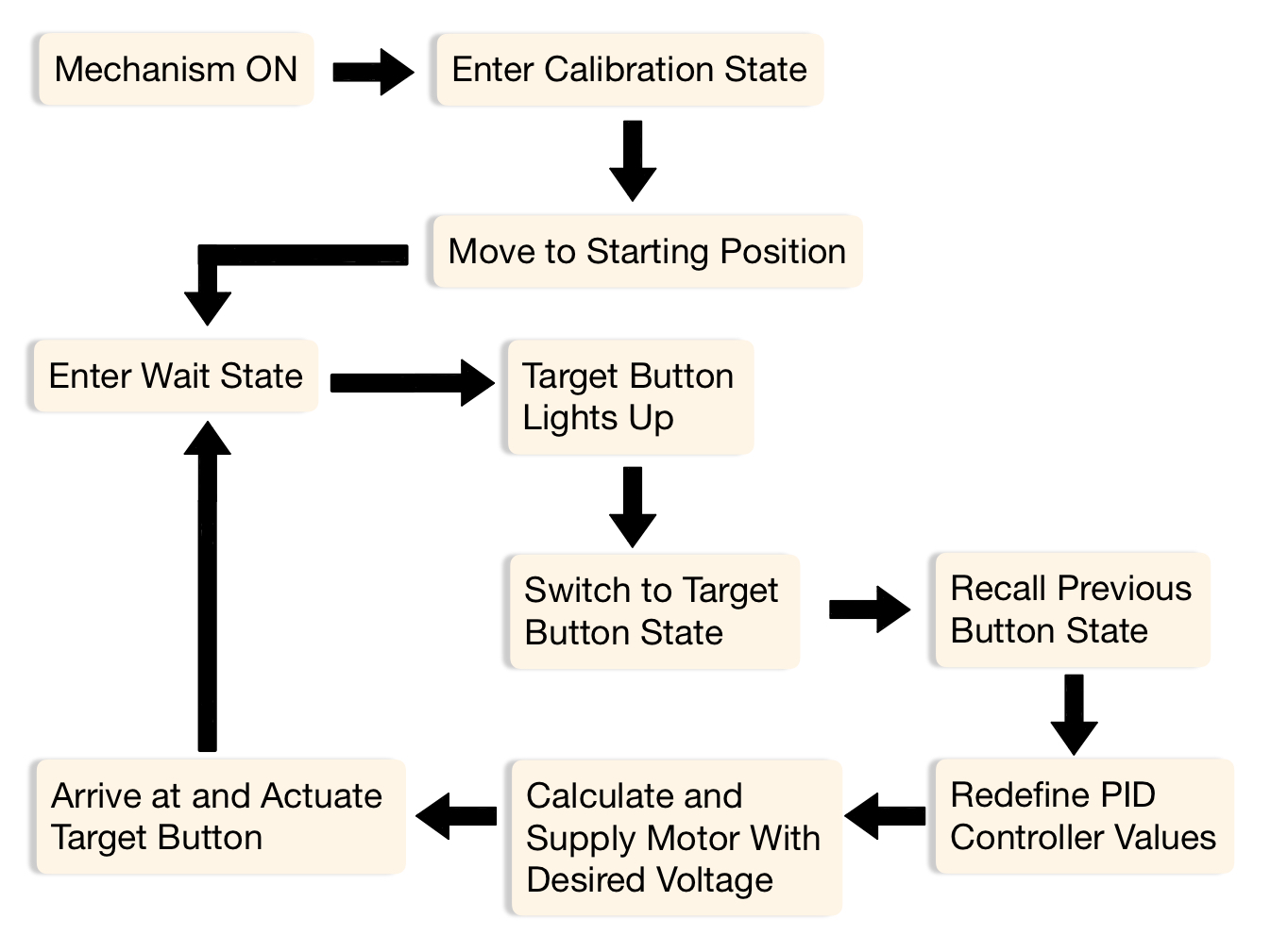
The Arduino IDE used to operate our mechanism was a PID Controlled State Machine. Each button on the board (Red, Blue, Yellow and Green) is fixed on the mounting board and its location is calibrated to its corresponding encoder count value within the DC motor. During operation, the DC motor rotates until the encoder count matches the target button. This brings the coupler of the mechanism to the button to be pressed.
When the mechanism turns on it enters the Calibration State. Here a default voltage is supplied to the motor which moves the mechanism to the starting first button position. Hitting the hard stop limit switch transitions the mechanism to the Wait State. The mechanism then waits for a target button to light, which reads in a high value to a digital pin on the Arduino. This signals the transition to the state correlated with the target button. Once in the new state, the target position is updated and the PID values (Kp, Kd, and Ki) are updated based upon the previous state. The PID values are used to calculate the desired PWM voltage and output to the motor. As the coupler approaches the button position, the supplied voltage decreases according the specified PID values and the solenoid actuates the buttons. This logic cycle continues until the time limit of 1 minute is reached.
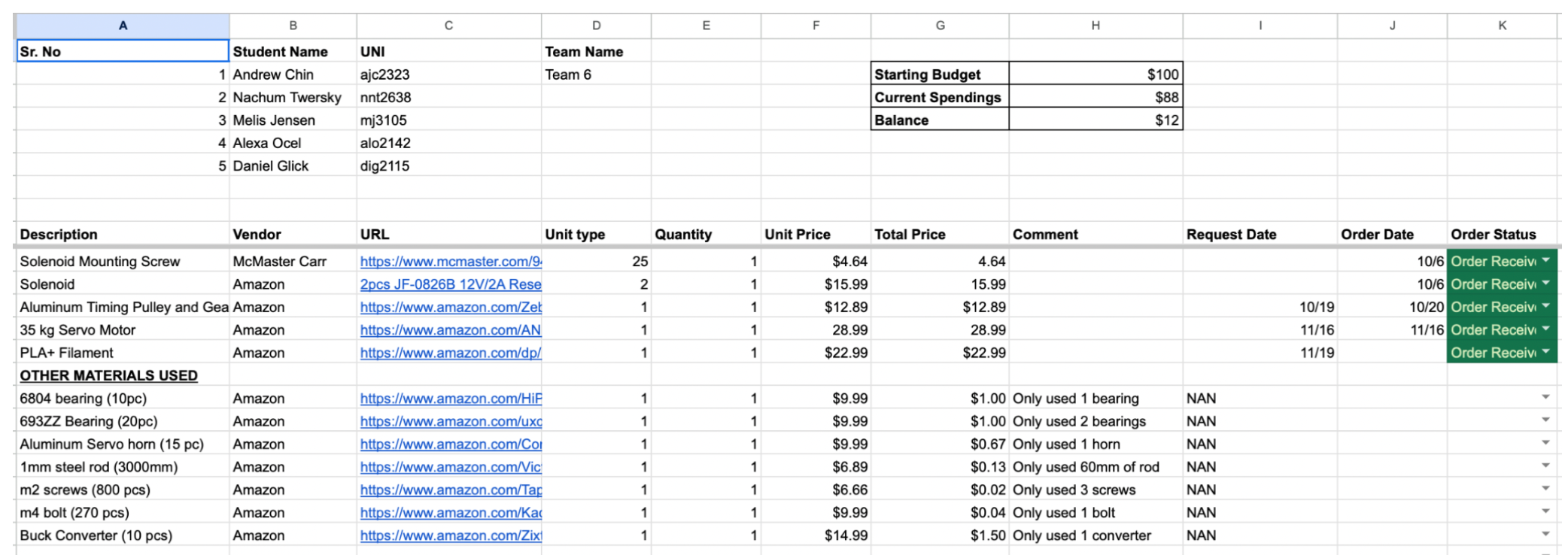
Budget
Below is the budget sheet used to track our team's finacial expenditures. Note that we remained underbudget with $12 left of our $100 allotment.