Scissor Jack Project Overview
As part of my machining course, I designed and fabricated a fully functional scissor jack. This project involved translating detailed mechanical drawings into precision-machined parts, generating G-code for tool paths within SolidWorks CAM, adhering to strict tolerances, and applying best practices in machining and assembly. The final scissor jack was evaluated based on machining accuracy and craftsmanship.
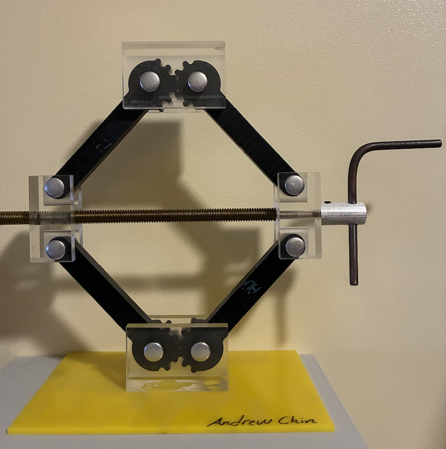
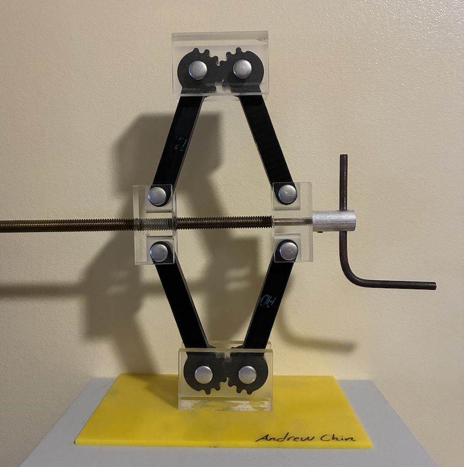
Functionality
Machining Process & Results
Generated Tool Paths - SolidWorks CAM
The individual parts were modeled within SolidWorks based upon the provided engineering drawings. Utilizing the SolidWorks CAM tool the tool paths were generated for the appropriate tools including end mills for slotting and perimeter cutting, spot drills for pilot holes, and drills for drilling out holes in a pecking manner.
Final Machined Parts
The project required extensive use of CNC Tormach milling machines, lathes, bandsaws, drill presses and taps. Tolerances were carefully monitored, and surface finishes were optimized to minimize friction in the final assembly. All parts were cut from the stock material on the bandsaw and machined to their appropriate outer dimensions.
The following major skills were employed to machine these parts:
- CNC Miling: facing, edge finding, measuring and inputting tool offsets, and utilizing conversational code
- Lathing: facing, turning, drilling
Delrin Links
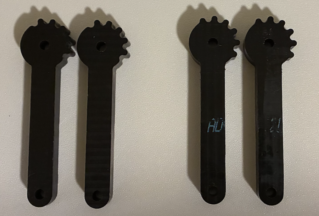
Bandsaw & CNC Tormach Mill
Acrylic Joint Blocks
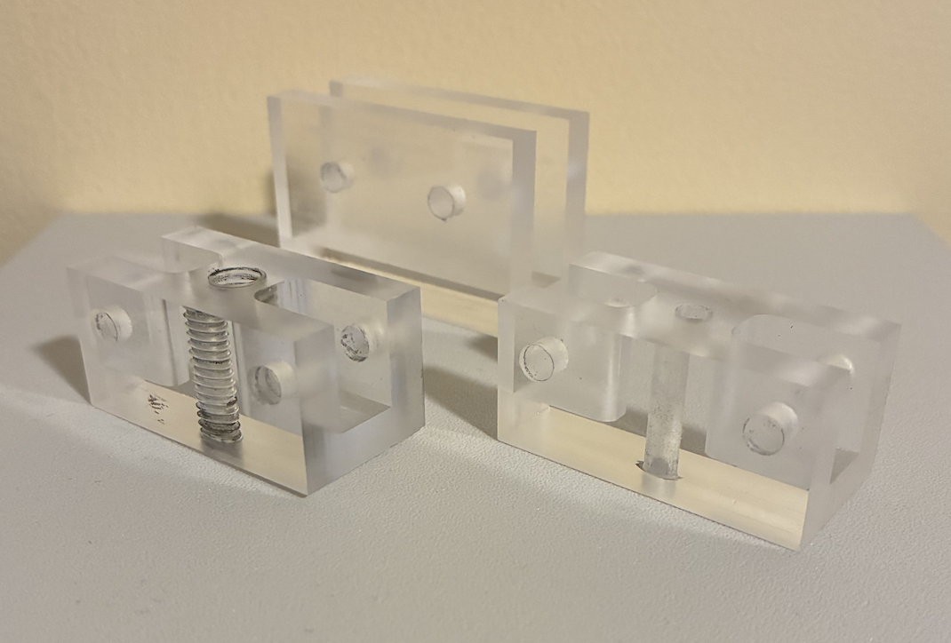
Bandsaw, CNC Tormach Mill, Drill Press & Tapping
Aluminum Handle Cap
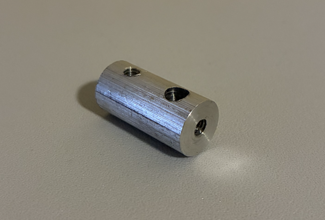
Lathe, Drill Press, & Tapping
Brass Threaded Rod
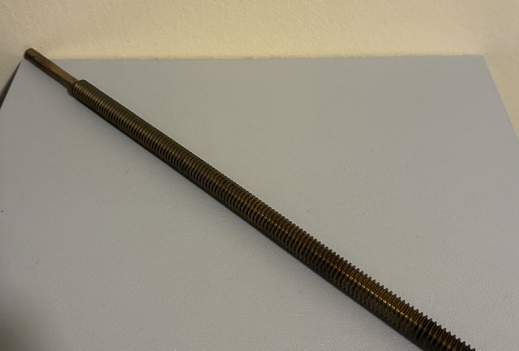
Lathe
Final Assembly
After completing the machining phase, all components were assembled into the final scissor jack mechanism. Alignment was checked to ensure smooth operation of the screw and linkage arms. The assembled device demonstrated a clean finish and precise motion.